
At Mobnia we pride ourselves in building digital products that help you succeed. But how do you build a software product that is reliable and robust? This is the fifth in a series of posts that address this question.
The high-level design provides an abstract level view of the system. It shows how application components interact while specifying assumptions about the run-time environment of the finished application. It should also describe development hardware and software as well as production hardware. It doesn't focus on the details of how application components work, however.
The Big Picture
Software development can be said to involve chopping up a system into smaller and smaller bits until said bits are small enough to implement. High-level design is basically the first chop. It divides the system into chunks that are self-contained enough for individual teams to implement.
On large projects, you may want to break these chunks down again before assigning them. Some projects also call for assigning multiple pieces to a single team, especially if the pieces are closely related or work with the same data structure/database table.
What to Specify
There are some common items you'd want to specify in the high-level design:
Security
Your high-level design should sketch out all the app's security needs. They may include:
-
Operating System Security: This includes types of login procedures, password policies and standards.
-
Application Security: Some apps rely on operating system security alone. Others use said security to make the user reenter the username and password or use a separate app username and password. App security means providing the right level of access to different users.
-
Data Security: You need to protect user data from
Facebookhackers. -
Network Security: You also need to protect the network connection.
-
Physical Security: Easy to overlook but the hardware also needs protection.
Hardware
With the various hardware platforms available these days, you need to specify what you'll use and if need be, what components of your system will be running on which hardware.
User Interface
You should sketch out the user interface at a high level. Specify modes of navigation, forms and screens to display to the user, etc. Walk through user stories and use cases and make sure you've handled them all. You don't need to go down to the details like specifying labels and text boxes though.
Internal Interfaces
You need to specify how the chunks of your application will interact so that the assigned teams can work independently without needing constant coordination. These internal interactions need to be specified clearly and unambiguously so that misunderstandings don't occur.
External Interfaces
Applications may need to work with external systems so you need to specify how they'll interact. These can be easier to specify than internal ones because you don't have control over both ends of the interface. The existing system will already have its own interface requirements.
Architecture
This describes how application components fit together at a high level. Different architectures are used for different types of systems. Here are some of the most common:
Monolithic
Here, a single program does everything that the application needs to do. It makes the system rigid since components are tightly coupled. It also demands that you understand how all the components fit together from the beginning of the project. It does have some advantages, however, as there's no need for complicated communication across networks. The architecture is useful for small applications with smaller development teams.
Client/Server
This architecture separates application components that need to use a function (clients) from the components that provide that function (servers). Both are decoupled so that they can be developed separately.
You could make the program two-tier. This makes it easier to support multiple clients on the same server, but both are relatively tightly coupled. To reduce this, you could introduce a middle tier between the two to make it three-tier. This provides insulation between client and server, eg: an interface that can map data between the formats that each of them uses. You can also define other multi-tier architectures.
Component-based
Here, you regard the system as a loosely coupled collection of components providing services for each other. Components are decoupled as in a multi-tier architecture, but they are all contained within the same executable program, so they communicate directly instead of over a network.
Service-oriented
This is similar to a component-based architecture except the components are implemented as services. A service is a self-contained program that runs on its own and provides some kind of service for its clients.
Data-centric
These come in a variety of flavors that all use data in some central way. Here are some typical designs:
- Storing data in a relational database system.
- Using tables instead of hard-wired code to control the application.
- Using stored procedures in the database to perform calculations and implement business logic.
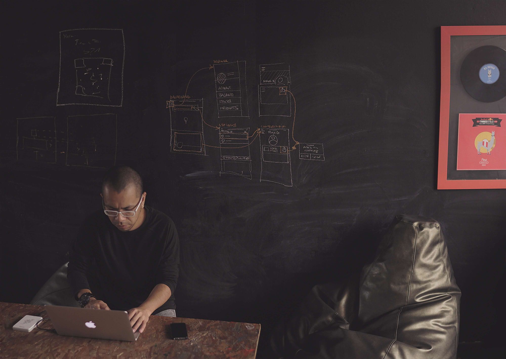
 Photo by Carlos Muza on Unsplash
Event-driven
Here, various parts of the system respond to events as they occur.
Rule-based
This uses a collection of rules to decide what to do next. They work well you identify the rules necessary to get the job done. They don't work well in an unexpected situation or if the problem is poorly defined. You should give the user a way to handle special situations manually.
Distributed
Here, different parts of the application run on different processors, perhaps concurrently. The processors could be on different computers scattered across a network or they could be in the same computer. They can be confusing and hard to debug. Race conditions also occur. If you get them right, however, you can improve performance.
Mix and Match
Different pieces of the application may use different architectures. Your customer support system may be rule-based while the rest of the system may be client/server.
Reports
Projects, especially large ones, use reports of some kind. For a game perhaps, you may want to track information on how users play and use the data to generate reports to help you refine the game and improve marketing. Decide which reports you need and leave the details for low-level design and implementation.
Other Outputs
The application might create other kinds of outputs (printouts, web pages, images, audio, etc).
Database
You need to decide how your application will store data. If you're using an external database, you need to specify the database product you'll use. If you use a relational database, you need to sketch out your tables and their relationships. More details can be provided later. Three common issues you should address here are audit trails, user access, and database maintenance.
Audit Trails
This keeps track of the user who modifies/views a specific record. It can be as simple as creating a history table that records a name, date, and link to the modifies record. The important thing is that you can then compare records over time to build a trail that recreates the exact sequence of changes made. In some cases, they aren't advisable so you can skip them.
User Access
Users have different access levels to data. There should be a way for your database to handle user privileges.
Database Maintenance
Over time, databases become cluttered with outdated data. These can be moved to another location to keep the database lean and responsive. There you can store, analyze or simply discard it. You also need to re-index key tables periodically or run tuning software on the database. In high-reliability applications, you'll want to do these during off-peak hours.
You should also have a backup and recovery scheme. The method varies with the size of the application. These tasks need to be in the plan.
Configuration Data
You can save yourself time if you provide configuration screens so users can fine-tune the application without making you write new code. You need to ensure only the ones with the right access level can do this.
Data Flows and States
Applications use data that flows through different processes. Events can sometimes make them take different paths through the system as well. The flows and states can be diagrammed to describe the system and the way the processes interact with data.
Training
Its never too early to think about the training material. You'll want to decide how you want it to work and define some high-level content. Should it be provided via videos? Blog posts?
UML
This defines several kinds of diagrams you can use to represent application components. UML 2.0 defines thirteen diagram types divided into three categories as shown:
- Structure Diagram
- Class Diagram
- Composite Structure Diagram
- Component Diagram
- Deployment Diagram
- Object Diagram
- Package Diagram
- Profile Diagram
- Behavior Diagram
- Activity Diagram
- Use Case Diagram
- State Machine Diagram
- Interaction Diagram
- Sequence Diagram
- Communication Diagram
- Interaction Overview Diagram
- Timing Diagram
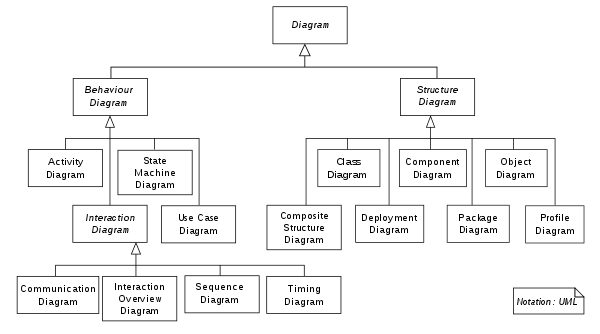 Courtsey of Wikipedia
Structure Diagrams
This describes things that will be in the system you're designing. Here are the different structure diagrams:
-
Class Diagram: Describes the classes that make up the system, their properties, methods, and relationships.
-
Object Diagram: Focuses on a particular set of objects and their relationships at a specific time.
-
Component Diagram: Shows how components are combined to form larger parts of a system.
-
Composite Structure Diagram: Shows a class's internal structure and the collaborations that the class allows.
-
Package Diagram: Describes relationships among system packages.
-
Deployment Diagram: Describes the deployment of artifacts on nodes (the platform).
Behavior Diagrams
UML defines three kinds of these: activity diagrams, use diagrams, and state machine diagrams.
Activity Diagrams
This represents the workflows for activities. They include several kinds of symbols connected with arrows to show the direction of the workflow.
Use Case Diagram
This represents a user's interaction with the system. They show stick figures representing actors connected to tasks by ellipses. To provide more detail, sub-tasks are joined to tasks by arrows. The annotation <<include>> means the task includes the sub-task. If the sub-task might only occur only under some circumstances, connect it to the main task and add the <<extend>> annotation.
State Machine Diagram
This shows the states through which an object passes in response to various events. Arrows indicate transitions from one state to another. Sometimes annotations on the arrows indicate what causes a transition. A black circle represents the starting state and a circled black circle indicates the stopping state.
Interaction Diagrams
These are a subset of activity diagrams. They include the following:
Sequence Diagram
This shows how objects collaborate in a particular scenario. It represents this as a sequence of messages. It basically shows in the order in which they occur, the interactions that occur between objects.
Communication Diagram
This also shows communication among objects, but rather than focusing on the sequence of messages, it focuses on the collaborating objects. The exact timing of the messages and some details aren't well represented here.
Timing Diagram
This shows object state changes over time. It resembles a sequence diagram turned sideways, so time goes from left to right. They're useful for understanding how long different parts of a scenario will take.
Interaction Overview Diagram
This is basically an activity diagram where the nodes can be frames containing other diagrams. The nodes could contain the sequence, timing, or even other interaction overview diagrams. Diagramception.